APC 940-0024 pinout used with Smart-UPS and Back-UPS Pro models.
APC part number 940-0024 (commonly encountered as 940-0024C) is the black smart signalling cable that connects the 9-pin D-Sub serial port on APC Smart-UPS and Back-UPS Pro units to a PC serial port. It carries a bidirectional ASCII serial protocol operating at 2400 bps, 8 data bits, no parity, 1 stop bit, enabling full two-way communication between the UPS and management software such as APC PowerChute Plus, PowerChute Pro, and compatible open-source tools. The cable has been the standard smart interface for APC UPS models sold since approximately 1996; it is compatible with tower Smart-UPS platforms (SU, SUA, SUM, SURT prefixes) but not with newer rack models that use a keyed RJ45 port. The UPS-end connector uses a non-standard pin assignment: TxD appears on pin 1 and RxD on pin 2, the reverse of standard RS-232; connecting a straight-through serial cable directly to the UPS port risks triggering a shutdown of the connected computer.
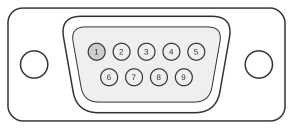 9 pin D-SUB male connector to the UPS
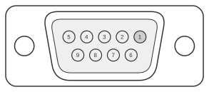 9 pin D-SUB female connector to the PC
| UPS Signal Name | DB-9 Male (UPS end) | DB-9 Female (PC end) | PC Signal Name |
|---|---|---|---|
| TX / AC Fail | 2 | 2 | Rx, Received Data |
| RX / Shutdown | 1 | 3 | Tx, Transmitted Data |
| Common | 9 | 5 | GND |
Notes
- At the PC end: pins 1,4 (DCD, DTR) shorted; pins 7,8 (RTS, CTS) shorted.
- The loopback connections on the PC-end (pins 1, 4, 7, 8 tied) allow PowerChute software to identify the cable type; they are not required for the NUT apcsmart driver.
- The UPS-end pin assignment is non-standard: TxD is on pin 1 and RxD is on pin 2, the reverse of normal RS-232. A standard straight-through DB9 cable must not be substituted — it would connect the PC’s DTR/RTS lines to the UPS on/off control input and risk shutting down the connected computer.
- Smart-UPS models also expose the Advanced Port features on the same connector: pin 7 provides remote on/off (momentary ~1 s HIGH turns the UPS on; momentary ~1 s LOW turns it off), and pin 8 provides an unregulated +24 Vdc supply current-limited to 50 mA (approximately ±10 V tolerance). The Smart-UPS 250 supplies only 18 Vdc at pin 8. These signals are not present on Back-UPS Pro or Smart-UPS v/s.
- Serial protocol parameters: 2400 bps, 8N1, software flow control. Commands are single ASCII characters; newer third-generation units also support two-byte command sequences.
Signals
- TX / AC Fail (UPS pin 2 → PC pin 2 RxD) — UPS transmit data; carries smart protocol responses and, in simple-signalling context, transitions LO→HI (RS-232 voltage level) when the UPS switches to battery power.
- RX / Shutdown (UPS pin 1 ← PC pin 3 TxD) — UPS receive data; accepts smart protocol commands from the host. When held at a HIGH RS-232 level for approximately 6 seconds (during on-battery operation), initiates a UPS shutdown.
- Common (UPS pin 9 → PC pin 5 SG) — chassis-referenced signal ground for the interface.